 roanbrasil
 UML Diagrams — Practical Reference
UML (Unified Modeling Language) is a standardized notation for visualizing software designs. Use the right diagram type for the question you're answering. This skill covers the diagrams you will actually use: class, sequence, state machine, activity, use case, and package.
Diagram Selection Guide
What are you documenting?
│
├── Static structure (what exists)
│   ├── Domain model, class relationships, API contracts → Class Diagram
│   ├── Module / package dependencies                   → Package Diagram
│   └── Replaceable components with provided/required interfaces → Component Diagram
│
└── Dynamic behavior (what happens)
    ├── Message flow between objects/services            → Sequence Diagram
    ├── Business process, algorithm steps, workflow      → Activity Diagram
    ├── Object lifecycle (states an entity moves through)→ State Machine Diagram
    └── User requirements / scope definition             → Use Case Diagram
Structural Diagrams
Class Diagram
Purpose: Model domain entities, their attributes, methods, and the relationships between them.
When to use:
- Explaining a domain model to a new team member
- Designing an API contract before implementation
- Documenting a design pattern implementation
- Architecture review: does the code structure match the design?
Notation Reference
Visibility:
  +  public
  -  private
  #  protected
  ~  package (default)

Class box:
  ┌─────────────────────┐
  │    ClassName        │  ← name (bold)
  ├─────────────────────┤
  │ - attribute: Type   │  ← attributes
  │ # count: int        │
  ├─────────────────────┤
  │ + method(): void    │  ← methods
  │ + find(id): Order   │
  └─────────────────────┘

Interface (<<interface>> stereotype or lollipop notation):
  ┌─────────────────────┐
  │   <<interface>>     │
  │   OrderRepository   │
  ├─────────────────────┤
  │ + save(o: Order)    │
  │ + findById(id): Order│
  └─────────────────────┘
Relationship Types — ASCII
Association    A has a reference to B (navigable)
  Customer ──────────────> Order

Aggregation    B can exist without A (weak ownership)
  Team ◇────────────────> Player

Composition    B cannot exist without A (strong lifecycle ownership)
  Order ◆────────────────> LineItem

Inheritance    B extends A (is-a relationship)
  Animal <|──────────────── Dog

Implementation B implements interface A
  OrderRepository <|·········· JpaOrderRepository

Dependency     A uses B transiently (in a method parameter or local var)
  OrderService ·············> EmailService

Multiplicity notation:
  1        exactly one
  0..1     zero or one
  *        zero or many
  1..*     one or many
  2..5     specific range
PlantUML — Class Diagram (E-Commerce Domain)
@startuml OrderDomain
skinparam classAttributeIconSize 0
skinparam monochrome true

title Order Domain Model

interface OrderRepository {
    +save(order: Order): Order
    +findById(id: OrderId): Optional<Order>
    +findByCustomerId(customerId: CustomerId): List<Order>
}

class Order {
    -id: OrderId
    -customerId: CustomerId
    -status: OrderStatus
    -items: List<LineItem>
    -shippingAddress: Address
    -createdAt: Instant
    +addItem(product: Product, qty: int): void
    +removeItem(productId: ProductId): void
    +confirm(): void
    +ship(): void
    +cancel(): void
    +totalAmount(): Money
}

class LineItem {
    -productId: ProductId
    -productName: String
    -unitPrice: Money
    -quantity: int
    +subtotal(): Money
}

class Address {
    -street: String
    -city: String
    -postalCode: String
    -country: String
}

class Money {
    -amount: BigDecimal
    -currency: Currency
    +add(other: Money): Money
    +multiply(factor: int): Money
}

enum OrderStatus {
    PENDING
    CONFIRMED
    SHIPPED
    DELIVERED
    CANCELLED
}

class Customer {
    -id: CustomerId
    -email: String
    -name: String
    -shippingAddresses: List<Address>
}

class JpaOrderRepository {
    -entityManager: EntityManager
    +save(order: Order): Order
    +findById(id: OrderId): Optional<Order>
    +findByCustomerId(customerId: CustomerId): List<Order>
}

Order "1" *-- "1..*" LineItem : contains
Order "1" *-- "1" Address : ships to
LineItem "1" -- "1" Money : priced at
Order "1" -- "1" OrderStatus : has status
Customer "1" -- "0..*" Order : places
OrderRepository <|.. JpaOrderRepository : implements
Order ..> Money : uses

@enduml
Mermaid — Class Diagram
classDiagram
  direction TB

  class Order {
    -OrderId id
    -CustomerId customerId
    -OrderStatus status
    -List~LineItem~ items
    +addItem(product, qty) void
    +confirm() void
    +ship() void
    +totalAmount() Money
  }

  class LineItem {
    -ProductId productId
    -String productName
    -Money unitPrice
    -int quantity
    +subtotal() Money
  }

  class Money {
    -BigDecimal amount
    -Currency currency
    +add(Money) Money
    +multiply(int) Money
  }

  class OrderStatus {
    <<enumeration>>
    PENDING
    CONFIRMED
    SHIPPED
    DELIVERED
    CANCELLED
  }

  class OrderRepository {
    <<interface>>
    +save(Order) Order
    +findById(OrderId) Optional~Order~
  }

  class JpaOrderRepository {
    -EntityManager em
    +save(Order) Order
    +findById(OrderId) Optional~Order~
  }

  Order "1" *-- "1..*" LineItem : contains
  Order --> OrderStatus : has
  LineItem --> Money : priced at
  OrderRepository <|.. JpaOrderRepository : implements
  Order ..> Money : uses
Package Diagram
Purpose: Show module/package dependencies. Detect circular dependencies before they become problems.
When to use:
- Enforcing Clean Architecture or Hexagonal Architecture boundaries
- Visualizing which modules are allowed to depend on which
- Identifying dependency cycles
@startuml PackageDependencies
skinparam monochrome true

title Package Dependencies — Clean Architecture

package "com.example.interfaces" {
    [OrderController]
    [InventoryController]
}

package "com.example.application" {
    [PlaceOrderUseCase]
    [ShipOrderUseCase]
    [OrderPort]
    [PaymentPort]
}

package "com.example.domain" {
    [Order]
    [LineItem]
    [OrderStatus]
    [Money]
}

package "com.example.infrastructure" {
    [JpaOrderRepository]
    [StripePaymentAdapter]
    [KafkaEventPublisher]
}

[OrderController] --> [PlaceOrderUseCase]
[OrderController] --> [ShipOrderUseCase]
[PlaceOrderUseCase] --> [Order]
[PlaceOrderUseCase] --> [OrderPort]
[PlaceOrderUseCase] --> [PaymentPort]
[JpaOrderRepository] --> [OrderPort]
[StripePaymentAdapter] --> [PaymentPort]

note "Domain has NO outbound dependencies.\nApplication depends only on Domain.\nInfrastructure implements Application ports." as N1

@enduml
Behavioral Diagrams
Sequence Diagram
Purpose: Show message exchanges between participants (actors, systems, objects) over time. The vertical axis is time; each participant has a lifeline.
When to use:
- API interaction flows (what calls what, in what order)
- Use case walkthroughs (step-by-step system behavior)
- Microservice choreography (who publishes, who consumes)
- Debugging: documenting what actually happened in an incident
Notation Reference
Participants:
  actor     Human user (stick figure)
  boundary  System boundary / UI
  control   Orchestrator / use case
  entity    Domain object / database

Message types:
  ->        Synchronous call (solid arrow)
  -->       Return message (dashed arrow)
  ->>       Asynchronous message (no wait for response)
  -->>      Async return

Combined fragments:
  alt       if/else (like a switch)
  opt       optional (executes only if condition true)
  loop      repetition
  par       parallel execution
  ref       reference to another diagram

Activation bars: narrow rectangle on lifeline = object is active
PlantUML — Sequence Diagram: Place Order Flow
@startuml PlaceOrderSequence
skinparam monochrome true
autonumber

title Sequence: Customer Places Order

actor Customer
boundary "React SPA" as SPA
control "Order API\n(OrderController)" as API
control "PlaceOrderUseCase" as UC
entity "Order" as Order
database "PostgreSQL" as DB
entity "KafkaEventPublisher" as Kafka

Customer -> SPA : Clicks "Place Order"
activate SPA

SPA -> API : POST /orders\n{items, shippingAddress}
activate API

API -> API : Validate JWT token\nextract customerId

API -> UC : placeOrder(customerId, items, address)
activate UC

UC -> Order : new Order(customerId, items, address)
activate Order

Order -> Order : validateItems()\ncheckInventory()

alt inventory available
    Order --> UC : Order (PENDING)
    deactivate Order

    UC -> DB : save(order)
    DB --> UC : Order (id assigned)

    UC -> Kafka : publish(OrderPlacedEvent)
    activate Kafka
    Kafka --> UC : ack
    deactivate Kafka

    UC --> API : OrderResponse
    deactivate UC

    API --> SPA : 201 Created\n{orderId, status: PENDING}
    deactivate API

    SPA --> Customer : "Order confirmed! ID: #1234"

else inventory unavailable
    Order --> UC : throw InsufficientStockException
    deactivate Order
    deactivate UC

    API --> SPA : 409 Conflict\n{error: "Item out of stock"}
    deactivate API

    SPA --> Customer : "Sorry, item unavailable"
end

deactivate SPA

@enduml
Mermaid — Sequence Diagram
sequenceDiagram
  autonumber
  actor Customer
  participant SPA as React SPA
  participant API as Order API
  participant UC as PlaceOrderUseCase
  participant DB as PostgreSQL
  participant Kafka

  Customer->>SPA: Clicks "Place Order"
  SPA->>API: POST /orders {items, address}
  activate API
  API->>API: Validate JWT
  API->>UC: placeOrder(customerId, items, address)
  activate UC

  alt inventory available
    UC->>DB: save(order)
    DB-->>UC: Order{id, status: PENDING}
    UC->>Kafka: publish(OrderPlacedEvent)
    Kafka-->>UC: ack
    UC-->>API: OrderResponse
    deactivate UC
    API-->>SPA: 201 Created {orderId}
    deactivate API
    SPA-->>Customer: "Order confirmed #1234"
  else inventory unavailable
    UC-->>API: 409 InsufficientStock
    deactivate UC
    deactivate API
    SPA-->>Customer: "Item unavailable"
  end
State Machine Diagram
Purpose: Document all states an entity can be in, the events that trigger transitions, and optional guards and actions.
When to use:
- Order lifecycle (PENDING → CONFIRMED → SHIPPED → DELIVERED)
- Payment state machine
- Connection state machine (DISCONNECTED → CONNECTING → CONNECTED → ERROR)
- User account status
- Any entity where invalid state transitions cause bugs
Notation Reference
[*]         Initial state (filled circle) or final state
State       Rectangle with rounded corners
Transition  Labeled arrow: event [guard] / action
PlantUML — Order State Machine
@startuml OrderStateMachine
skinparam monochrome true

title Order State Machine

[*] --> PENDING : Order created

PENDING --> CONFIRMED : confirm()\n[payment successful]
PENDING --> CANCELLED : cancel()\n[within 30 min]

CONFIRMED --> PICKING : warehouseAssign()
CONFIRMED --> CANCELLED : cancel()\n[admin only]

PICKING --> PACKED : packingComplete()
PICKING --> CONFIRMED : unassign()\n[warehouse error]

PACKED --> SHIPPED : shipmentDispatched(trackingNumber)

SHIPPED --> DELIVERED : deliveryConfirmed()
SHIPPED --> RETURN_REQUESTED : customerRequestsReturn()\n[within 30 days]

DELIVERED --> RETURN_REQUESTED : customerRequestsReturn()\n[within 30 days]

RETURN_REQUESTED --> RETURNED : returnReceived()

RETURNED --> REFUNDED : refundIssued()

CANCELLED --> [*]
DELIVERED --> [*]
REFUNDED --> [*]

note right of PENDING
  Entry action: Send order confirmation email.
  Timeout: Auto-cancel after 30 min if payment fails.
end note

note right of SHIPPED
  Entry action: Send shipment notification with tracking URL.
end note

@enduml
Mermaid — State Machine
stateDiagram-v2
  [*] --> PENDING: Order created

  PENDING --> CONFIRMED: confirm() [payment OK]
  PENDING --> CANCELLED: cancel() [within 30 min]

  CONFIRMED --> PICKING: warehouseAssign()
  CONFIRMED --> CANCELLED: cancel() [admin only]

  PICKING --> PACKED: packingComplete()
  PACKED --> SHIPPED: shipmentDispatched(trackingId)

  SHIPPED --> DELIVERED: deliveryConfirmed()
  SHIPPED --> RETURN_REQUESTED: requestReturn() [< 30 days]
  DELIVERED --> RETURN_REQUESTED: requestReturn() [< 30 days]

  RETURN_REQUESTED --> RETURNED: returnReceived()
  RETURNED --> REFUNDED: refundIssued()

  CANCELLED --> [*]
  DELIVERED --> [*]
  REFUNDED --> [*]
Activity Diagram
Purpose: Flowchart-style diagram showing steps in a process, with decisions (diamonds), parallel execution (fork/join bars), and swimlanes to show which actor performs each action.
When to use:
- Business process documentation (checkout flow, return flow)
- Algorithm steps (especially with branching and parallel steps)
- Workflow documentation with multiple actors
PlantUML — Activity Diagram with Swimlanes: Checkout Process
@startuml CheckoutActivity
skinparam monochrome true

title Activity: Checkout Process

|Customer|
start
:View cart;
:Enter shipping address;
:Select shipping method;

|Payment Service|
:Display payment form;
:Validate card details;

if (Card valid?) then (yes)
    :Authorize payment;
    if (Authorization approved?) then (yes)

        |Order Service|
        :Create order (PENDING);
        :Reserve inventory;
        fork
            :Send order confirmation email;
        fork again
            :Notify warehouse;
        end fork
        :Set order status to CONFIRMED;

        |Customer|
        :Show order confirmation;
        stop

    else (declined)
        |Customer|
        :Show payment error;
        :Retry or change payment method;
        stop
    endif
else (no)
    |Customer|
    :Show validation error;
    stop
endif

@enduml
Mermaid — Flowchart (Activity-style)
flowchart TD
  A([Start: Customer clicks Checkout]) --> B[Enter shipping address]
  B --> C[Select shipping method]
  C --> D[Enter payment details]
  D --> E{Card valid?}

  E -->|No| F[Show validation error]
  F --> D

  E -->|Yes| G[Authorize payment]
  G --> H{Authorization approved?}

  H -->|Declined| I[Show payment error]
  I --> J([End: Customer retries])

  H -->|Approved| K[Create Order - PENDING]
  K --> L[Reserve inventory]
  L --> M[Set status CONFIRMED]

  M --> N[Send confirmation email]
  M --> O[Notify warehouse]

  N --> P([End: Show order confirmation])
  O --> P
Use Case Diagram
Purpose: Show what the system does (use cases) and who does it (actors). Not for technical design — for scope definition and stakeholder alignment.
When to use:
- Project kickoff: defining system scope
- Stakeholder sign-off on features
- Identifying actors and their goals
Keep minimal. Use cases are ovals with verb phrases ("Place Order", "Track Shipment"). Never use Use Case diagrams to show technical implementation.
@startuml UseCases
skinparam monochrome true

title Use Cases — E-Commerce Platform

left to right direction

actor "Customer" as customer
actor "Warehouse Staff" as warehouse
actor "Administrator" as admin

rectangle "E-Commerce Platform" {
    usecase "Browse Catalog" as UC1
    usecase "Add to Cart" as UC2
    usecase "Place Order" as UC3
    usecase "Track Shipment" as UC4
    usecase "Request Return" as UC5
    usecase "Authenticate" as UC_AUTH

    usecase "Fulfill Order" as UC6
    usecase "Update Inventory" as UC7
    usecase "Print Shipping Label" as UC8

    usecase "Manage Products" as UC9
    usecase "View Reports" as UC10
    usecase "Manage Users" as UC11
}

customer --> UC1
customer --> UC2
customer --> UC3
customer --> UC4
customer --> UC5

warehouse --> UC6
warehouse --> UC7
warehouse --> UC8

admin --> UC9
admin --> UC10
admin --> UC11

UC3 ..> UC_AUTH : <<include>>
UC6 ..> UC_AUTH : <<include>>
UC9 ..> UC_AUTH : <<include>>

UC3 ..> UC2 : <<include>>

@enduml
PlantUML in Practice
# Render locally
java -jar plantuml.jar diagram.puml        # outputs diagram.png
java -jar plantuml.jar -tsvg diagram.puml  # outputs diagram.svg
java -jar plantuml.jar -tpdf diagram.puml  # outputs diagram.pdf

# Render all .puml files in a directory
java -jar plantuml.jar docs/diagrams/*.puml

# Use PlantUML server (Docker)
docker run -d -p 8080:8080 plantuml/plantuml-server:jetty

# CI: generate PNGs and commit alongside source
# GitHub Actions example:
# - uses: cloudbees/plantuml-github-action@master
VS Code: Install "PlantUML" extension by jebbs. Alt+D to preview.
Embed in Markdown:
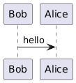
Use the PlantUML online server to generate PNG URLs, or use kroki.io as a proxy.
Mermaid in Practice
Native support in: GitHub Markdown, GitLab, Notion, Obsidian, Confluence (with plugin), HackMD, Azure DevOps.
```mermaid
classDiagram
  Animal <|-- Dog
  Animal : +name String
  Animal : +speak() void
  Dog : +breed String
**Diagram types:**
classDiagram → Class diagram sequenceDiagram → Sequence diagram stateDiagram-v2 → State machine flowchart TD/LR → Activity / flowchart (TD=top-down, LR=left-right) erDiagram → Entity-relationship C4Context → C4 Level 1 (via C4 plugin) C4Container → C4 Level 2 gitGraph → Git branching visualization
**Limitations vs PlantUML:**
- Less expressive for complex sequence fragments (`alt`/`loop` less powerful)
- No swimlane support in activity/flowchart
- Limited styling options
- Class diagram notation less complete (no package, no component)
- Mermaid's advantage: zero setup in GitHub/GitLab

---

## Anti-Patterns

| Anti-Pattern | Problem | Fix |
|---|---|---|
| Class diagram with every class | Diagram becomes noise; readers can't find the important relationships | Model only the concepts central to the design decision you're communicating |
| Sequence diagram without activation bars | Unclear when objects are active; concurrent calls become ambiguous | Use `activate`/`deactivate` or the shorthand `++`/`--` in PlantUML |
| State diagram with missing transitions | Implies illegal state transitions don't exist, leading to bugs | Every state needs every possible event handled (even if "ignore") |
| UML class diagram for system architecture | Wrong abstraction level and wrong audience | Use C4 Container/Component diagrams instead |
| Mixing relationship types | Composition arrows used for association, etc. | Standardize on one notation and document it in the team wiki |
| Arrows without multiplicity | "Has" could mean 1 or 1000 — matters for performance and design | Always add multiplicity to both ends of every association |
| Diagram rot | Diagrams committed as PNG, source never updated | Commit source (`.puml`, `.mermaid`), generate PNG in CI; or use living tools |

---

## Quick Reference — PlantUML Class Relationships

```plantuml
' Association (A navigates to B)
A --> B

' Aggregation (weak: B can exist without A)
A o-- B

' Composition (strong: B lifecycle owned by A)
A *-- B

' Inheritance (B is-a A)
A <|-- B

' Interface implementation (B implements A)
A <|.. B

' Dependency (A uses B transiently)
A ..> B

' With multiplicity
A "1" *-- "1..*" B : contains

' With role labels
A "owner" --> "pet 0..*" B
Quick Reference — PlantUML Sequence Messages
A -> B : Synchronous call
A --> B : Return (dashed)
A ->> B : Async (no block)
A -->> B : Async return

activate A
deactivate A

alt condition
    A -> B : message
else other
    A -> C : message
end

loop for each item
    A -> B : process(item)
end

opt if condition is true
    A -> B : optional call
end